Note: This post contains many images that may require additional load time.
You’ve ordered your parts, they’ve arrived, and you are ready to build your computer! This is the fun part. I want to take a moment to acknowledge the amount of wasteful packaging involved with all of the individual components. I wish Newegg and the manufacturers would come together to develop packing materials that fit together like a build your own computer puzzle, as to reduce the amount of overall waste.
The first thing you’ll want to do is setup a clean, dust free, and well lit area to build your new computer. Wash your hands well and frequently throughout the build. Wear an anti-static wrist strap if you have one. If you don’t have one, don’t worry too much, but do be conscious of any movements that may build up a static electric charge. The most vulnerable components are the motherboard, processor, RAM, and graphics processor. Frequently discharge yourself on the steel portions of your case.
I like to start by assessing every component followed by removing the case side panels (usually attached with thumb screws in the back). You’ll notice some cables that come out of the front portion of the computer case, these are used to power the computer on and provide peripheral connections like audio or USB. We’ll worry about these once we have the motherboard installed, so feel free to tuck them away from the mounting area of the motherboard. In the case should be a box or bag containing a set of screws. Sort through these and identify their individual usage. Your case should come with a manual or reference printed on the box if you aren’t sure. The first set of screws you’ll want to find are referred to as “motherboard standoffs”.
Album one, prepping the case for the build.
[envira-gallery id=”124″]
Motherboards that adopt the sizing standard of ATX will require all of the available screw holes in your case, most likely. Extended ATX would present the only exception. Check out the manual included with your case, it should outline for you where to install these screws. There’s a good chance you’ll need to screw in nine of them, three on the top, three in the middle, and three on the bottom. I purchased two additional case fans, one to act as an exhaust for the top and another to act as an intake for the front of the case. Now is a good time to mount these as well.
Now, go ahead and mount your optical drives and card reader, if you have them. For this build, my case had thumb screws and quick detach covers for the front 5.25″ bays. Note at the end of this build the black bracket that surrounds the 3.5″ card reader, I had to order this to ensure that the card reader fit nicely into a 5.25″ bay seeing as my case did not include one. This is a Bytecc product at Newegg, about $15.
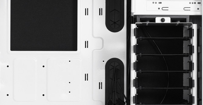
The last step before moving onto the motherboard is to mount the hard disks or solid state drives. The Define R4 case I bought for this build included two separate modular hard disk mounting areas. The top is easily removable and has the ability of holding five hard disks. I cannot imagine why anybody would ever need to do this, but it certainly is nice to know that you can in a $90 mid tower case. I had three hard disks from my old computer that I mounted along with two brand new Sandisk Extreme II solid state disks that nicely mounted behind the motherboard.
A Special note regarding the Define R4 SSD Mounts: These mounts make it difficult for the SATA cables to attach to the SSD’s, because they are flushly mounted to the case and some SATA cables come with “L Connector” ends. This causes a protrusion and can damage the SATA cables or the SSD’s if someone attempts to bend the L cable into place. I had to purchase two SATA power extension cables in order to get them to connect flush, because I had two SSD’s. Just search, “SATA Power Extension” on Newegg and you should encounter a Startech product, many other people have posted reviews stating that they used these extensions as a solution. The cost is about $9 per cable. I wish power supply manufactures did not ship “L Connectors” because they are a pointless feature.
Album two, mounting the standoffs, fans, and drives into the case.
[envira-gallery id=”164″]
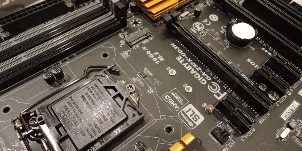
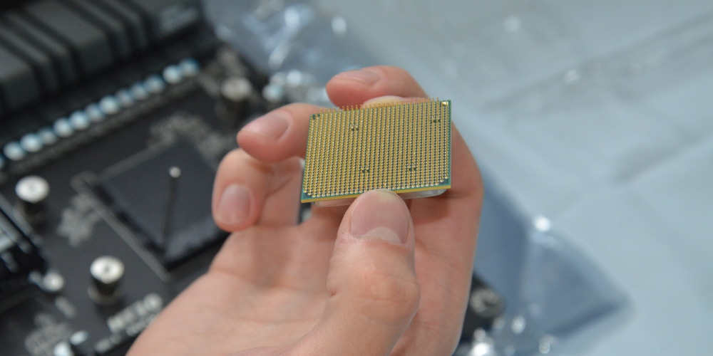
Now, remove the motherboard from it’s anti static bag and place it onto a clean surface. Depending on whether or not you purchased an upgraded CPU fan determines whether you need to remove the stock mounting brackets or not. I show removing them and installing the ones required by the 212 Evo, which are pretty substantial in comparison. Follow the 212 Evo directions the best you can, as they are marginally helpful. If you have troubles, watch this video. Now mount your processor while being aware of the arrows that match up. If you bend any of the pins, you will ruin your processor. This is sort of difficult to do because the processor drops in nicely if aligned correctly.
Do not touch the top face of the processor, be sure to wash and dry your hands before handling.
I apply the thermal paste pretty heavily. Be sure to apply it in a nice straight line or as a single dot (look up the recommended method of application, which can vary based on the processor architecture) without the possibility of creating any air bubbles. If you mess up, get a washcloth, remove it, and start over. Don’t sweat the tiny size of the tube, you’ll have plenty of thermal paste for about three applications. Check out this article on applying thermal paste. Mount the CPU cooler to exhaust out the back of the case (see pictures for more reference). Place the CPU cooler and try not to lift it once placed, screw down in a cross pattern, starting with the top left screw. Tighten down on the 212 Evo just before you reach the black plastic washer-stays, they serve as a good indicator. You can wiggle the cooler to help the thermal paste settle and spread.
Now, mount your RAM by carefully placing it into each slot as evenly as possible. If you purchased dual channel RAM, be sure to place one in the first slot of each DIMM module. And just before you mount the motherboard into the case, pop in the back plate for the rear I/O connections.
Album three, prepping and mounting the motherboard.
[envira-gallery id=”196″]
To finish up, mount the power supply and graphics card. To mount the power supply, simply place it into the shelf and screw in the four mounting screws at the rear bottom of the case. The graphics card can be mounted after removing the case PCI slot covers. Note the wireless card I installed as well. These cards are commonly referred to as PCI slot or PCI Express slot cards, this is the naming convention for the Peripheral Component Interconnect bus standard. Your graphics card runs on a very fast and modern version of this original bus standard, so it may include a mounting lock that clicks upon placing the graphics card onto the motherboard.
Re-secure these cards with the screws that secured the PCI slot covers. I would never recommend using tool less mounts that some cases have for these slots.
Album four, mounting the PSU and PCI cards.
[envira-gallery id=”218″]
In part four, we will discuss the process of wiring, cable management, and the first boot up of your new computer.